Computer Connection Diagram
COMPUTER CONNECTION DIAGRAMS
There are a lot of cables involved when getting a computer connected and ready to run. Also there are many different types of connection ports for the cables. This page will go into detail and show you not only where these cables connect, but I will also go into detail about each individual cable and it's function. Some cables can be made at home with the right connectors, So I will show pin-outs for these connectors so you will know which pin gets soldered to where.
Most computers today follow a common color code for the device ports located in the rear of your computer. But not all devices follow this color scheme, so this Computer Connection Diagram will help you to identify what devices go to each connection point. Granted, some devices are made to obviously go to a unique port but some are common to one another and may be inserted into the wrong ports.
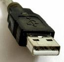
USB devices can be plugged into any USB port on your computer and will be recognized automatically. Some USB components may require a driver to be installed so it can be recognized by the computer and should be provided by the product manufacturer.
For a computer connection diagram, click on the picture below in order to get a closer look at the ports in which your computer components will attach.

|
This is the monitor cable connector. It is a 15 pin male connector that is usually blue or just plain white. Some monitors will have cable connectors on both ends of the cable, if so, the connectors will only mate one way, but most monitors will only have one end with a connector. The monitor side of the cable is usually a permanent connection. Be sure and snug this cable tight with the thumb screws provided on them because a loose connection will cause big headaches and can possibly cause monitor failure.

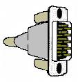
Computer Monitor 15-pin Connector Pin-Out Chart.

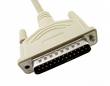
This is the printer cable connector. It is a 25 pin female connector that does not usually come in any specific color code like the other connectors. They will usually come with thumb screws just like the monitor cable connector, so be sure that you tighten this connector good and snug as well. Never over tighten as this will sometimes cause the screw port on the computer to come loose the next time you take off the printer cable. Just a good snug connection will be sufficient. This style printer connector is becoming obsolete. A lot of today's printers have USB connectors.
Printer Cable 25-pin Connector Pin-Out Chart.


|
These connectors are referred to as PS/2 connectors. They are a 6-pin round connector with a flat section that only allows them to go into the ports on the computer one way. These type connectors are for your keyboard and mouse connections. They are typically color coded so they are not inserted into the wrong ports on the computer. The PS/2 ports on the computer are identical to one another so be sure to match up to the proper color codes. The keyboard port is purple and the mouse or other pointer device is green.

PS/2 6-pin Connector Pin-Out Chart.

|
Speaker connections can come in a few different styles but the most common is a single prong connector. The most common type speakers will have a separate power cord for their electrical supply and a single wire that connects to the computers speaker output port. The speaker connector is typically colored green and will be inserted into the green port on your computer which is the audio-out connection. The red or pink connector is for audio-in such as a microphone. The blue connector is also audio-in in case you need more than one device connected such as an mp3 player.
|
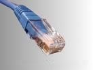
This picture is showing an RJ45 Connector. This will attach to the computers network adapter. Although it works the same and looks very similar to a phone connector, it is actually bigger because it has 8 wires versus 4 wires that is in a phone connector referred to as RJ11. A modem is an older technology that allowed you to connect a telephone line to your computer to access or "dial-up" the internet. Most newer computers do not have modems anymore but if you do have one in yours, it can still provide phone access and is useful to use as a Fax. Your modem of course should be a combination fax/modem which most are anymore. The RJ45 network cable has many purposes. Now most computers are configured to use the network adapter to access the internet via modem using the RJ45 connector. The network adapter is also used to build a network of computers together using cat5 cable.
|
The USB connector is the latest and now most common used connector. Your computer most likely has many USB ports because most external devices are utilizing the USB port to connect to computers. USB stands for Universal Serial Bus. Memory sticks, printers, digital camera's, MP3 Players and list goes on, all are now USB devices. The technology now has embedded drivers that allow for the computer to automatically recognize the device connected. The computer will automatically load a particular driver if that device is connected for the first time and then will recognize that device every time it's connected. If the computer is not able to identify the device connected, then chances are that your device came with a disc that has the driver necessary for your computer to recognize it.