How To Wire A Relay
Let's discuss how to wire a relay and go through the concepts of how a relay works.
A relay is basically a switch but not like a switch that's on a wall. A wall switch relies on someone to flip it which will then control a light or some other type load. A relay is switched by electrical power and not a human. This is done by energizing a coil which is internal to the relay and by energizing the coil, the relay changes state just like a wall switch would. Therefore when you energize a relay, you are switching circuits off and on.
Relays have many purposes and are used in a variety of ways such as electronic circuit boards, machines, appliances, automobiles and the list can go on. The main purpose of a relay is to switch electrical circuits off and on at given times and allow circuits to be automated. A great advantage with relays is the ability to switch many different circuits of different voltage types all at once by using the same relay.
Wiring Relays
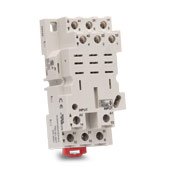
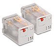
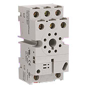
Although relays come in a huge variety of designs, shapes and sizes, They all basically work with the same concept. I'm going to be covering some industrial relay logic and the images you see here are some of the most common types used for industrial controls also called machine controls.
These images show a square 3-pole relay and it's socket on the left and a round 2-pole relay and it's socket on the right. The socket is used to connect your wires to the relay. This particular relay with 3-poles means you have 3 separate switches or what we'll call contacts.
3 Common
3 Normally Closed
3 Normally Open
A 2-Pole relay will contain 2 separate contacts.
2 common
2 Normally Closed
2 Normally Open
And So On.
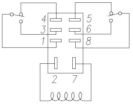
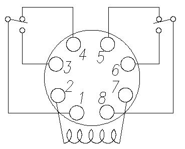
The square relay pinout shows how the relay socket is configured for wiring. This pinout image is only a 2-pole diagram for room on the page purposes, but you can get the picture here with this one since a 3-pole will just have 1 more set of contacts. As you can see, there is absolutely no difference between the square type and the round type other than the ratings on the relay. Otherwise they work exactly the same.
So when wiring up these relays, the coil wire's will connect to pins 2 & 7 on the socket.
One Pole Has:
Pin's 1 & 3 as Normally Open
Pin's 1 & 4 as Normally Closed
The Other Pole Has:
Pin's 8 & 6 as Normally Open
Pin's 8 & 5 as Normally Closed
See my Switch Terminology Page for more on contact arrangements if you need to.
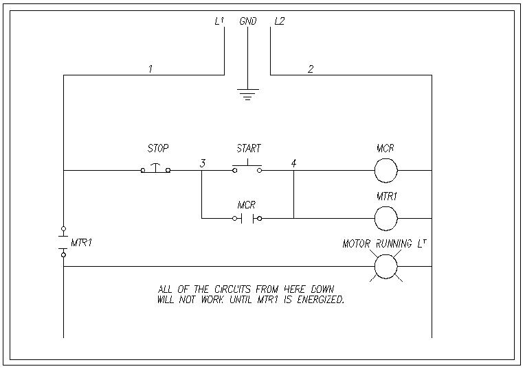
By looking at the diagram below we can go through the basic concept of a relay and how they operate. This diagram will show you how simple it is to control motors, lights, valves, other relays and any type load you want. In this example we are simply turning on a light.
Let's say were using household voltage in this circuit which is 110/120 Vac. L1=Hot and L2=Neutral. Just like basic house wiring, we always want to control (switch) the hot wire. So as you can see below, L1 goes down into a normally closed switch. This means the current travels through that switch until it see's an open switch and cannot go any further. In this case L1 is hot all the way to the START switch. When the start switch is depressed, L1 now goes to the relay coil MCR (Master Control Relay) and energizes the coil. Now the (2) MCR contacts which are normally open as shown will now close. This allows current flow through the contacts and energizes the light.
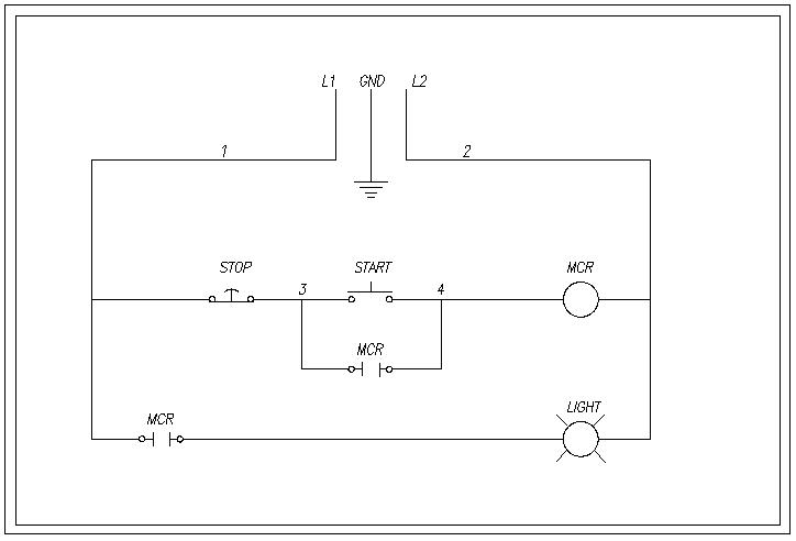
Now that the contact below the START switch is closed, you can now release the START switch and the current flow goes around the open START switch, through the contact to keep the relay coil energized which also keeps the light on. Now to turn the light off, you simply depress the STOP button and this will open the circuit to the relay, de-energizing the coil. The relay contacts open to their normal state and stop the current flow to the light. Once you let off of the STOP button the circuit is back to it's normal state with L1 waiting for the START button to be depressed.
There you have it. A relay circuit. Now these diagrams are known as relay logic or ladder diagrams. It's using relays to control the circuit and also the diagram will begin to take the shape of a ladder as the relay logic grows. It will continue downward as you will see later on.
Now in the diagram below I have added a motor starter. A motor starter is just another name for a certain type of relay that is used to control a motor. We'll call this MTR1(Motor1). The logic here is the same as above with the exception of adding control to the circuit so that any of the circuit below the MTR1 contact will not be hot until the MTR1 coil is energized, which closes the MTR1 contact. This allows current to flow to the lower part of the diagram (Not Shown) and turns on the "MOTOR RUNNING LIGHT".
